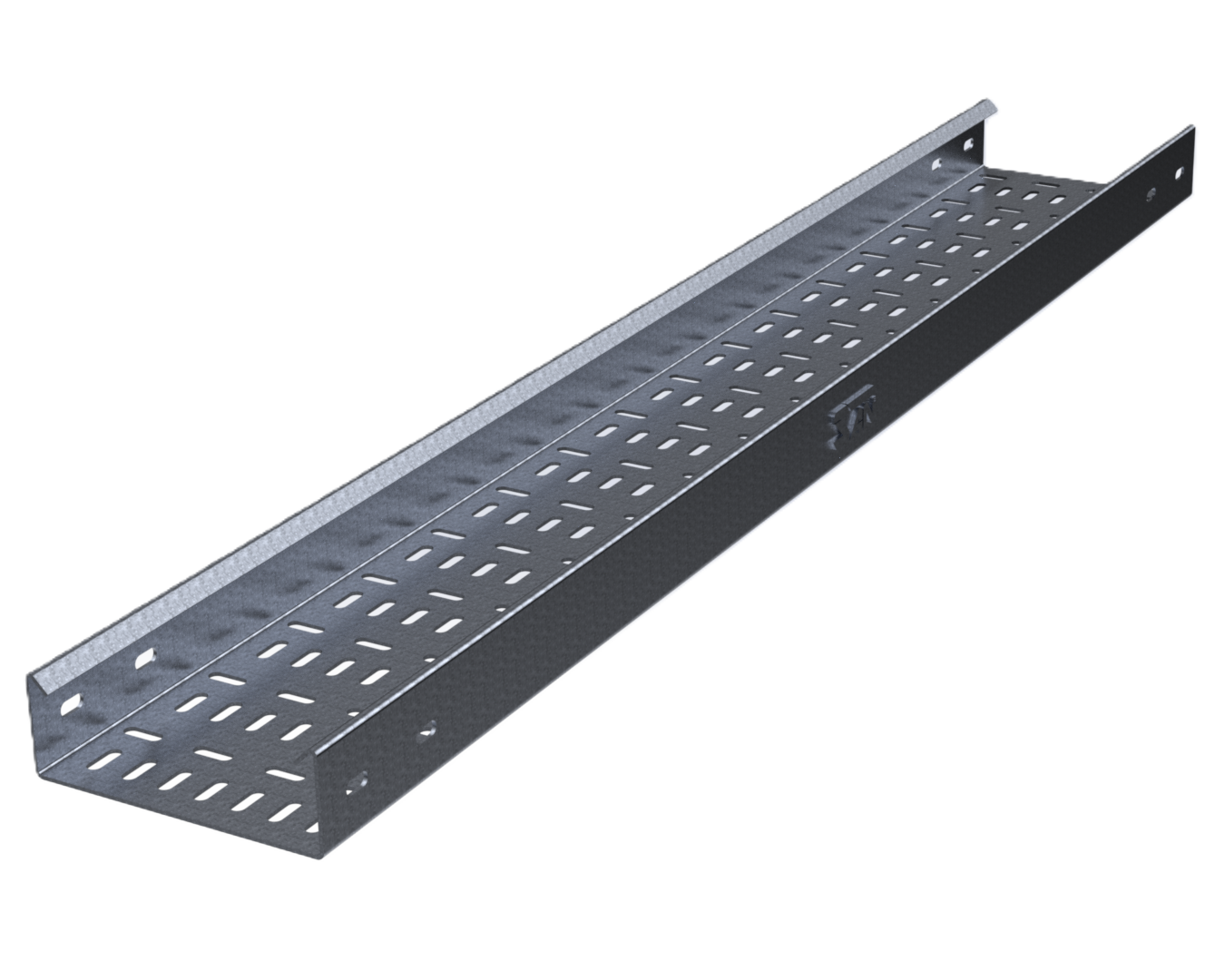
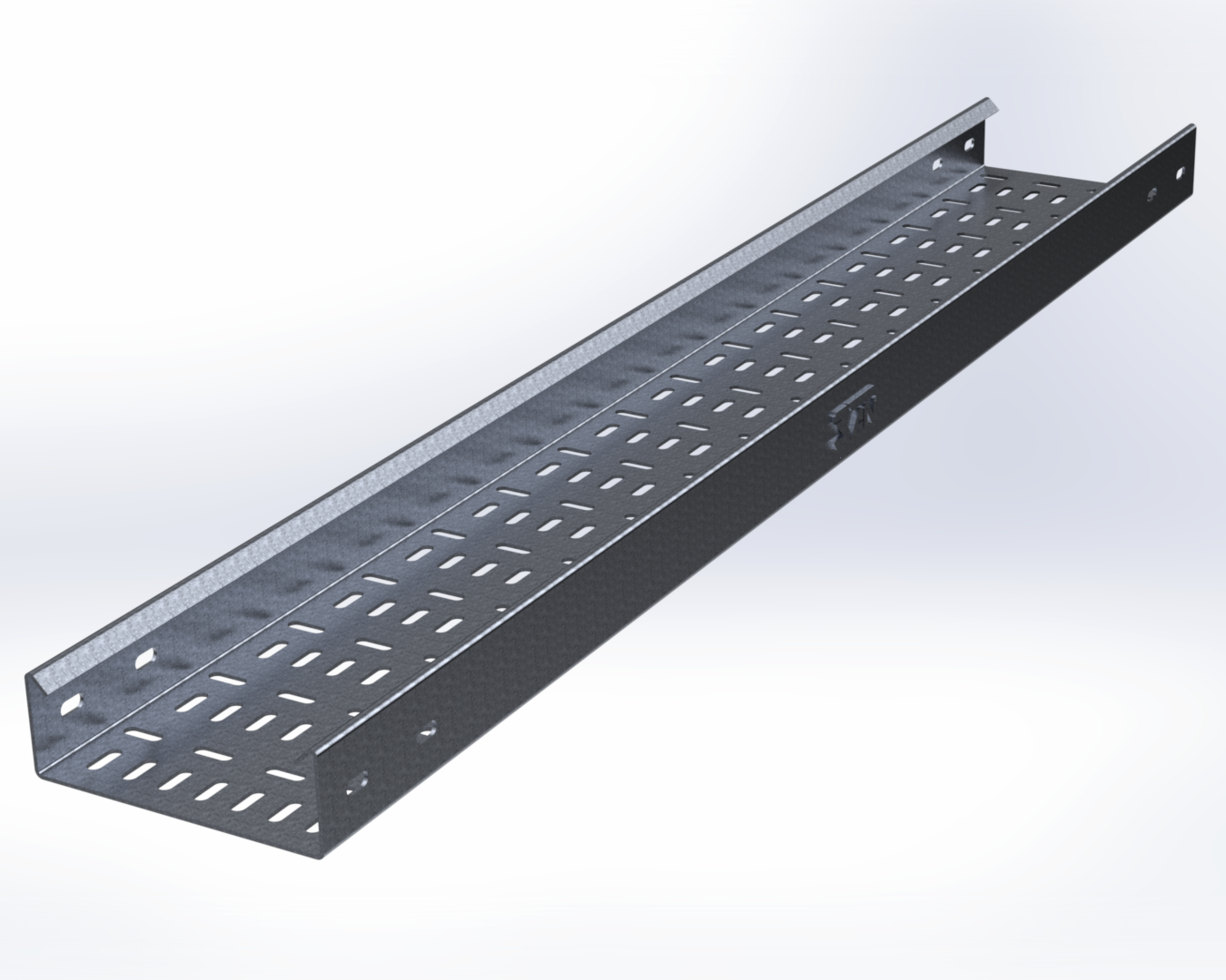
Cable Tray - SAN Engineering Malaysia

Cable Support System

Cable Tray Supplier in Malaysia

Buyer Guide

Need help selecting the right product? Read our educational guide before requesting a quotation.

Cable Tray — SAN Engineering Malaysia

Cable Tray System

NEMA VE 1 / MS / IEC 61537

Cable Ladder System

NEMA VE 1 / MS / IEC 61537

Cable Trunking System : MS 50085

Cable Tray Supplier in Malaysia

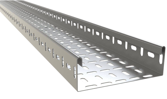
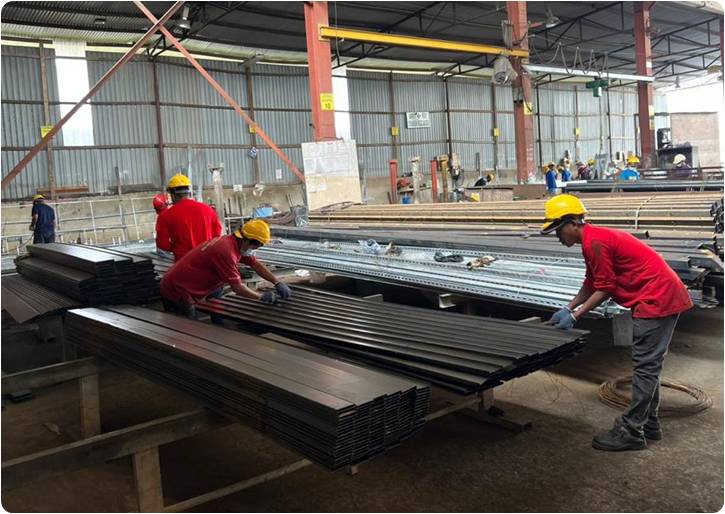
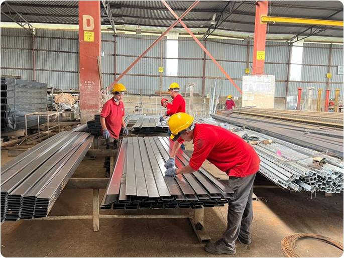
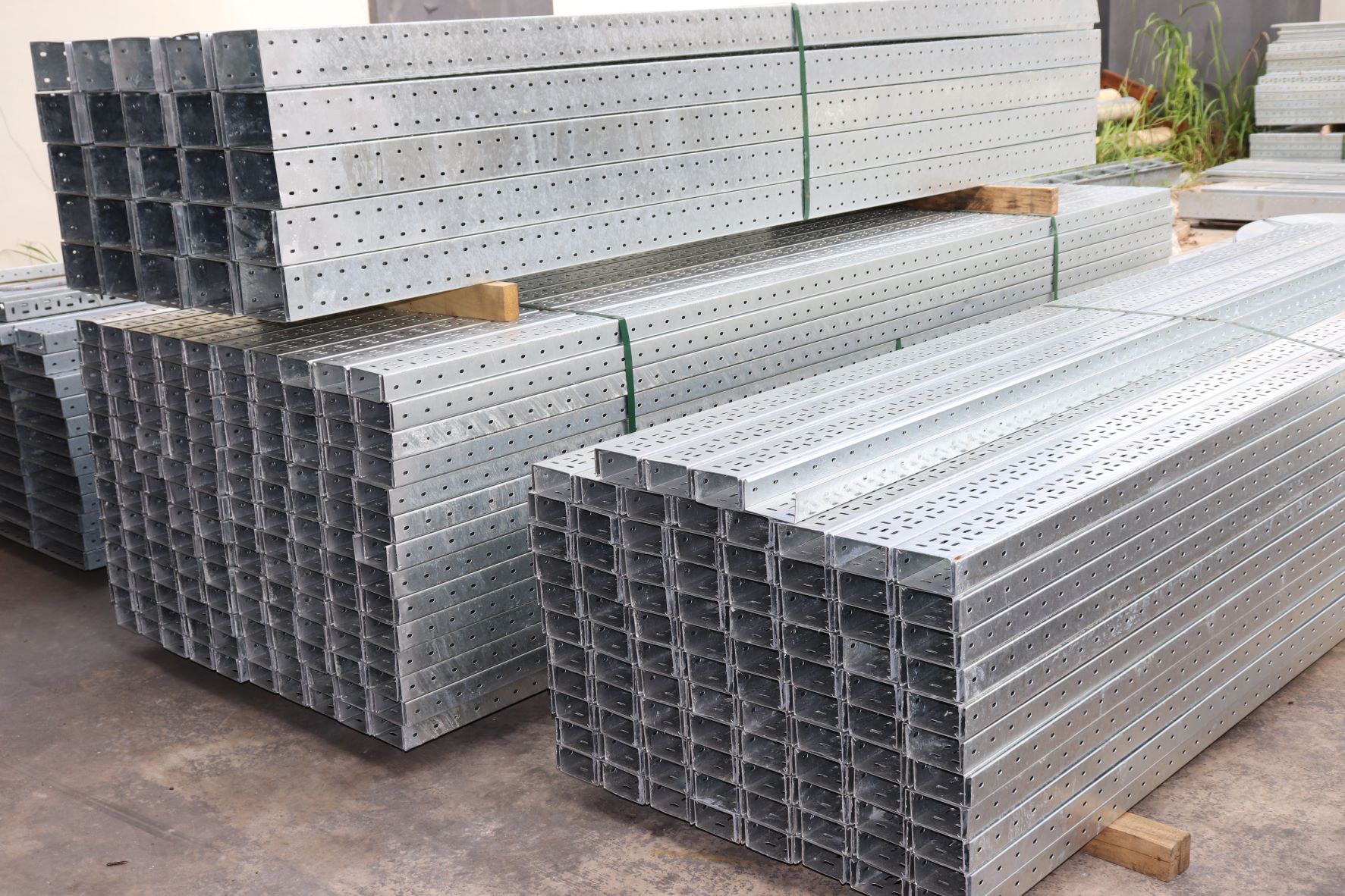
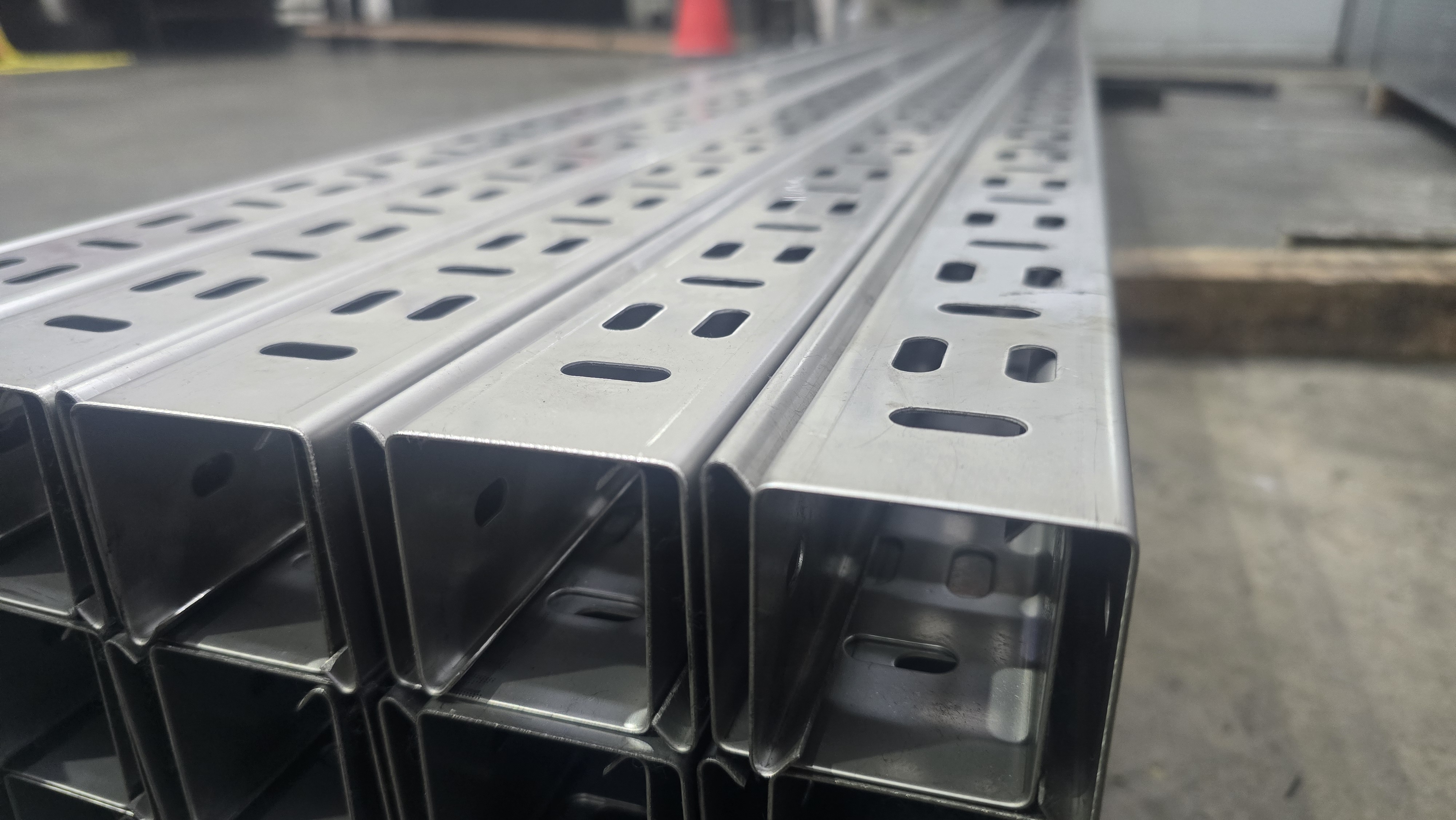
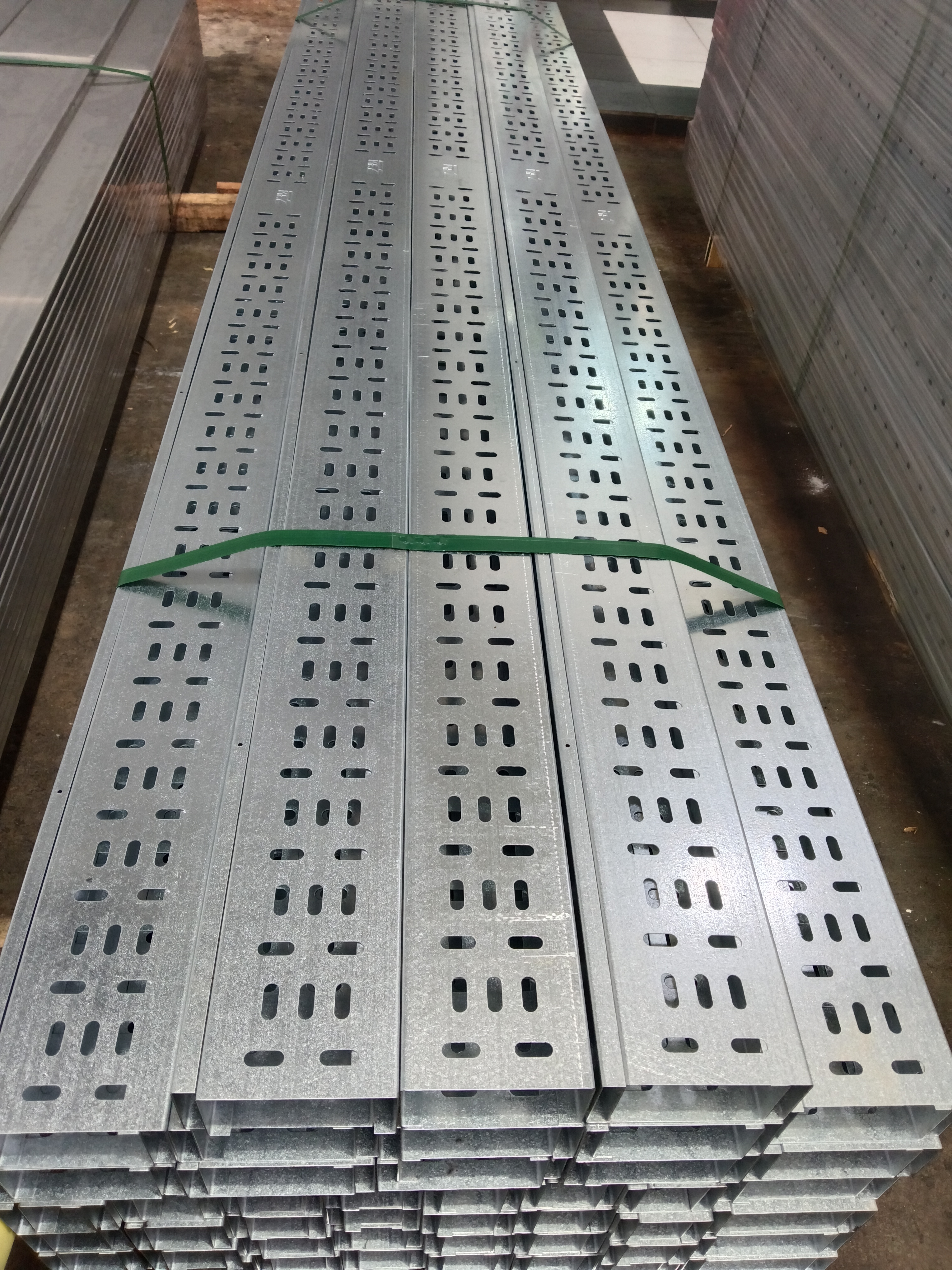
SAN Engineering and Electrical Support, a metal fabrication company, is one of the best cable tray suppliers in Malaysia. Our company manufactures high-quality hot dip galvanised (HDG) cable trays that meet the requirements of cable and electrical wire installations and conform to local and international standards of fabrication and finishing.

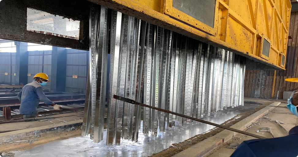
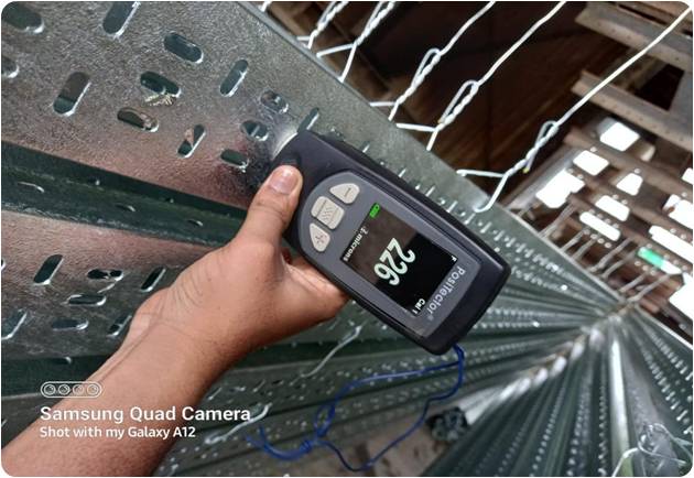
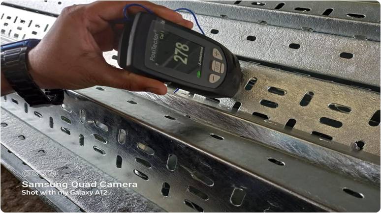
Our HDG cable trays are manufactured using top-grade steel that undergoes a thorough galvanisation process. SAN offers cable tray systems fabricated from corrosion-resistant steel, stainless steel and aluminum alloys, along with corrosion-resistant finishes, including zinc, PVC and epoxy. This process involves coating the steel with a layer of zinc, enhancing its resistance to corrosion, moisture, and other environmental factors.

As a cable tray supplier in Malaysia, we always prioritize customer satisfaction and strive to establish long-term partnerships with our clients. We offer a comprehensive range of cable tray options, including various sizes, configurations, and accessories, to meet your specific requirements. Our experienced team is ready to assist you in selecting the right cable tray solutions for your projects.

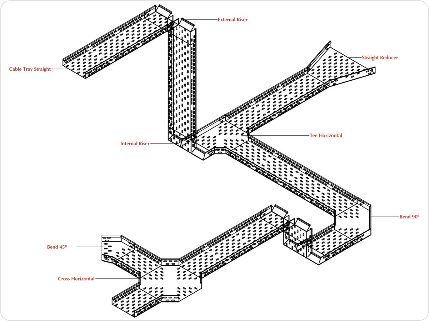
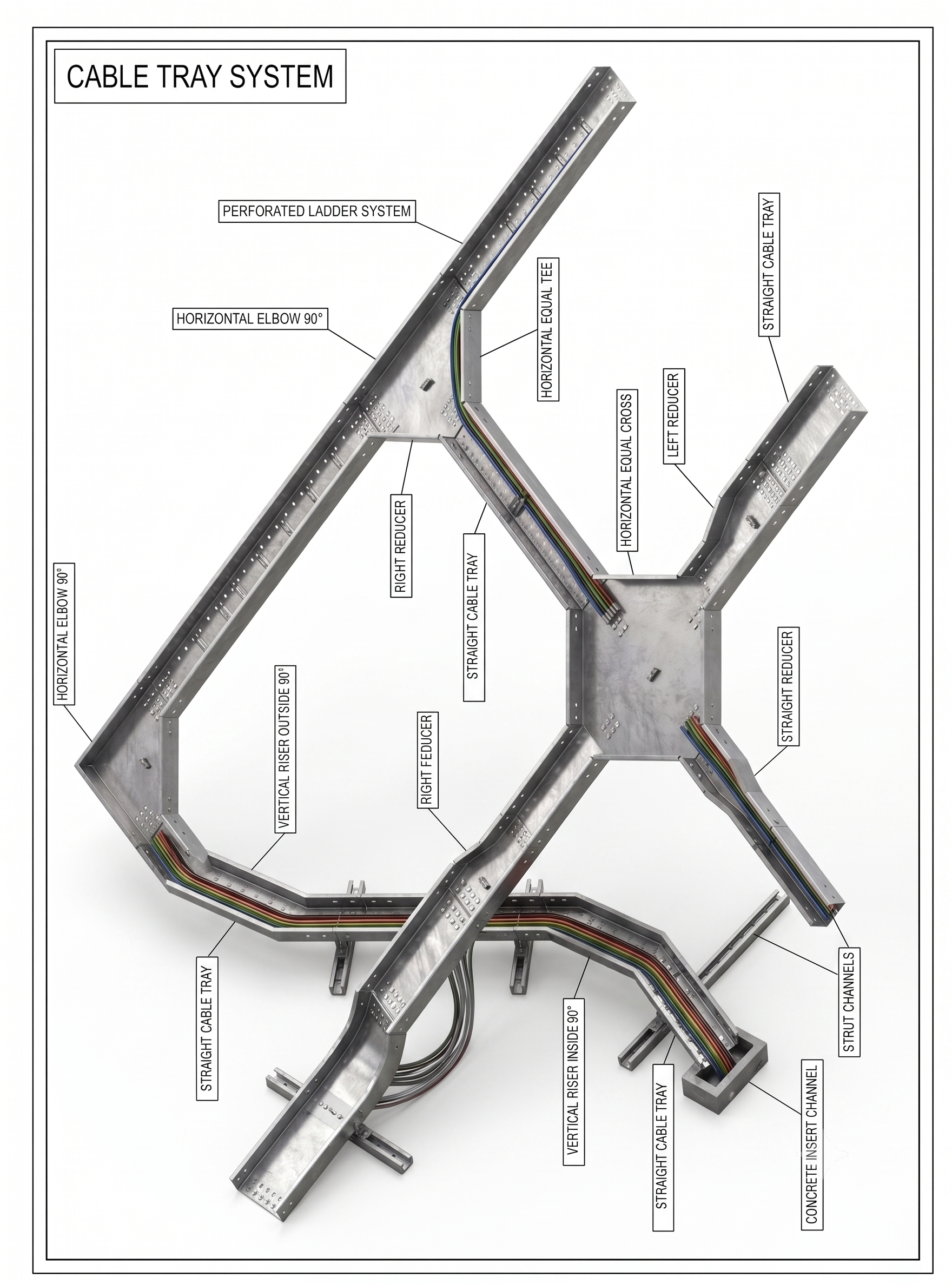
Cable Tray Layout

Typical cable tray routing and fitting arrangement.

Cable tray layout 1
Cable tray layout 2

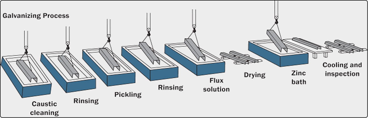
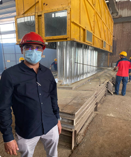
Hot-Dip Galvanization Process

Process visuals from the source page for HDG finishing.

Hot dip galvanization process overview
Hot dip galvanization process step 2
Hot dip galvanization process step 3
Hot dip galvanization process step 4
Hot dip galvanization process step 5
Hot dip galvanization process step 6
Hot dip galvanization process step 7

Compliance

SAN Engineering cable tray system compliance

SAN Engineering Cable Ladder Tray Systems, fittings and accessories are manufactured in compliance with:

  • IEC 61537 International Electrotechnical Commission (Cable management – Cable tray systems and cable ladder systems)
  • SASO IEC (61537/2007) Saudi Standard (Cable management – Cable tray systems and cable ladder systems)
  • NEMA VE 1 - 2009 National Electrical Manufacturers Association. (Metal Cable Tray Systems)
  • NEMA VE 1 class 20 C
  • NEMA VE 2 - 2006 National Electrical Manufacturers Association. (Metal Cable Tray Installation Guide Lines)
  • NEC (ANSI / NFPA 70) National Electric Code (Metal Cable Tray Guide Lines)

Cable Tray Selection Process – Guide

1. Select Material and Finish

The most suitable material and finish for your application will depend on cost, the potential for corrosion, and electrical considerations. SAN offers cable tray systems fabricated from corrosion-resistant steel, stainless steel and aluminum alloys along with corrosion-resistant finishes, including zinc, PVC and epoxy.

2. Select the Tray Class

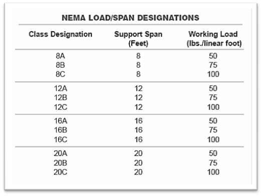
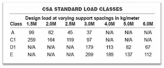
NEMA standard VE-1 defines 12 load classes. The classes are designated by a number (8,12, 16, and 20), specifying maximum span in feet and a letter (A, B, and C), specifying the maximum load (A = 50 lbs./ft., B = 75 lbs./ft., and C = 100 lbs./ft.). The load rating must include the weight of the cables plus any applicable wind or snow loads. The load capacity available for cable is therefore reduced for outdoor applications. Costs vary between different load classes. Since labor and coupling costs are similar for a given length of tray, the heavier classes are more cost effective on a load length basis. The designer should therefore specify the lightest class of tray compatible with the weight requirements of the cable tray.

3. Select the Tray Type

Cable tray is available with three styles of bottom:

Ladder Cable Tray is a prefabricated structure consisting of two longitudinal siderails connected by individual transverse members.

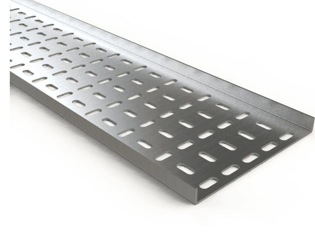
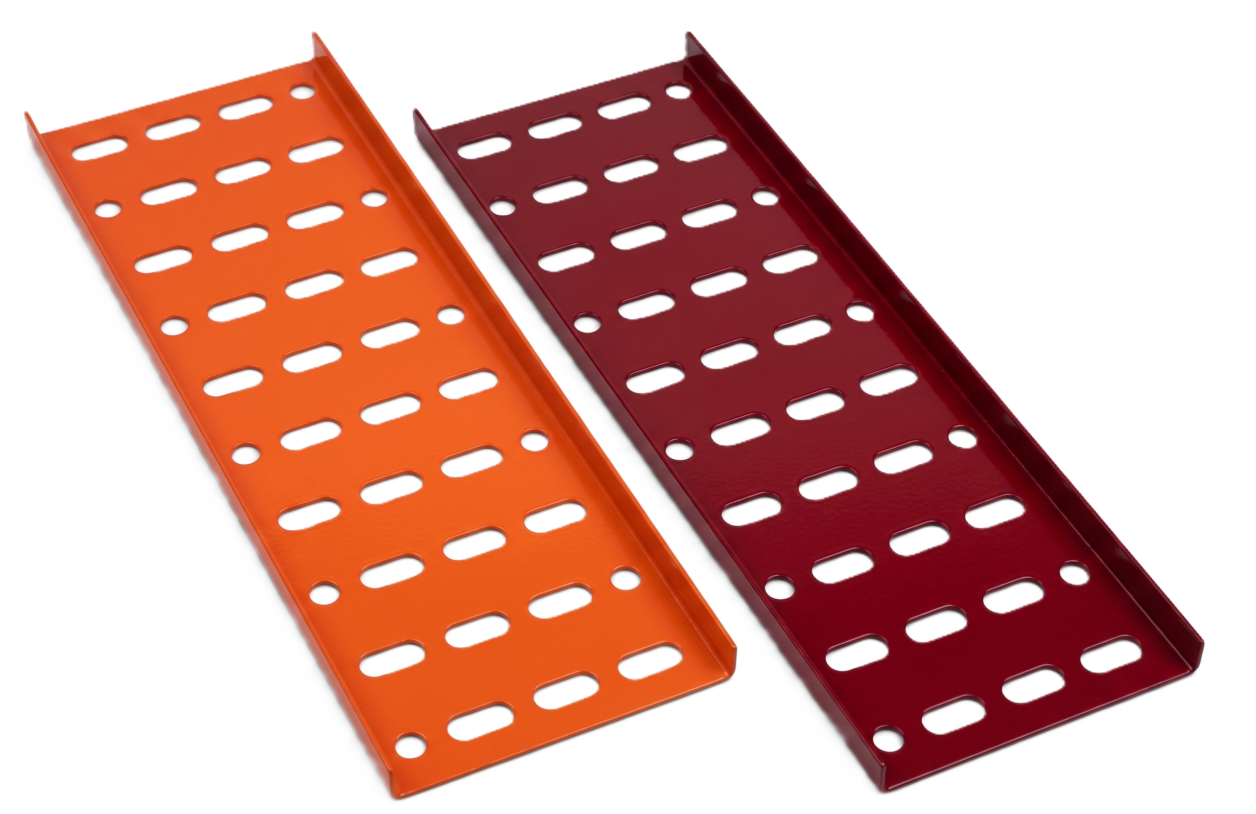
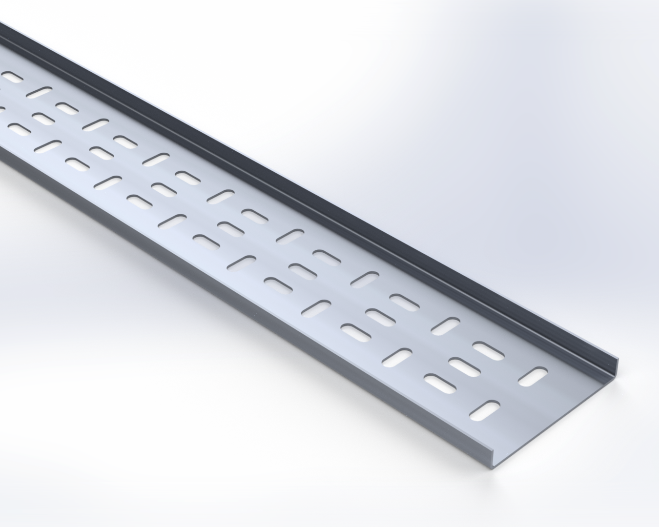
Ventilated Cable Tray is a prefabricated structure consisting of a ventilated bottom within integral or separate longitudinal siderails, with no openings exceeding 4 in. in a longitudinal direction.

Solid Bottom Cable Tray is a prefabricated structure without openings in the bottom. Ladder tray is most often used because of its cost effectiveness. The designer has a choice of four nominal rung spacings: 6, 9, 12, and 18 inches. The greatest rung spacing compatible with an adequate cable bearing surface area should be selected. Heavy power cables often require greater cable bearing area due to the possibility of creep in the jacket material of the cable. If this is a concern, consult the cable manufacturer. This condition may require the use of ventilated tray, which also offers additional mechanical protection for the cables.

systems under certain conditions. The designer should verify these before specifying the type of tray to be used. Electromagnetic shielded tray may be used in areas where control or data cables need to be protected from RFI interference. For more information, see the “Electromagnetic Shielded” section of this manual.
Cable tray type 1
Cable tray type 2

4. Select the Tray Size

The width or height of a cable tray is a function of the number, size, spacing and weight of the cables in the tray. Available nominal widths are 6, 9, 12, 18, 24, 30, 36 and 42 inches. When specifying width, it is important to remember that the load rating does not change as the width increases. Even with six times the volume, a 36 in. wide tray cannot hold any more weight than a 6 in. wide tray. If the load rating of the tray permits, cable can be piled deeper in the tray. Most tray classes are available in a nominal 3d, 4, 5, 6 and 7 inch height. Cable ties or other spacing devices may be used to maintain the required air space between cables.

5. Select the Fittings

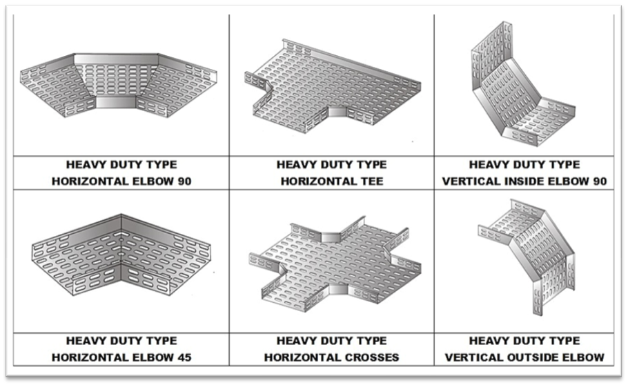
Fittings are used to change the size or direction of the cable tray. The most important decision to be made in fitting design concerns radius. The radius of the bend, whether horizontal or vertical, can be 12, 24, 36 or 48 in., or even greater on a custom basis. The selection requires a compromise with the considerations being available space, minimum bending radius of cables, ease of cable pulling, and cost. The typical radius is 24 in. Fittings are also available for 30°, 45°, 60°, and 90° angles. When a standard angle will not work, field fittings or adjustable elbows can be used. It may be necessary to add supports to the tray at these points.

6. Consider Deflection

Deflection of the cable tray affects the appearance of an installation, but it is not a structural issue. In the case of non-metallic cable tray, deflection may be affected by elevated temperatures.

NEMA Load Test.

The NEMA load test is a simple beam, uniformly distributed load test. This type of test was initially selected because:

  • It was easiest to test.
  • It represents the worst case beam condition compared to continuous or fixed configurations. When consulting the manufacturer’s catalog for deflection information, the designer must verify whether the data shown represents simple or continuous beam deflection. If continuous beam deflection is shown, the calculation factor should be given.

NEMA has one criterion for acceptance under their load test: the ability to support 150% of the rated load.
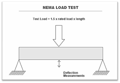
NEMA load test deflection reference

Simple vs. Continuous Beam Deflection.

Theoretical maximum deflection for a simple beam, uniformly distributed load may be calculated as: .0130 w L4 / E I

Where: w = Load in lbs./ft.

L = Length in inches

E = Modulus of Elasticity

I = Moment of Inertia

The maximum deflection calculation for a continuous beam of two spans with a uniformly distributed load is: .00541 w L4 / E I

A continuous beam of two spans therefore has a theoretical maximum deflection of only 42% of its simple beam deflection. As the number of spans increases, the beam behaves increasingly like a fixed beam, and the maximum deflection continues to decrease. As this occurs, the system’s load carrying capability increases.
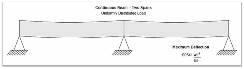
Simple vs continuous beam deflection

Since different bending moments are created in each span, there is no simple factor to approximate deflection as the number of spans increases. It is possible to calculate these deflections at any given point by using second integration of the basic differential equation for beams. Testing shows that the center span of a three-span cable tray run can deflect less than 10% of its simple beam deflection.
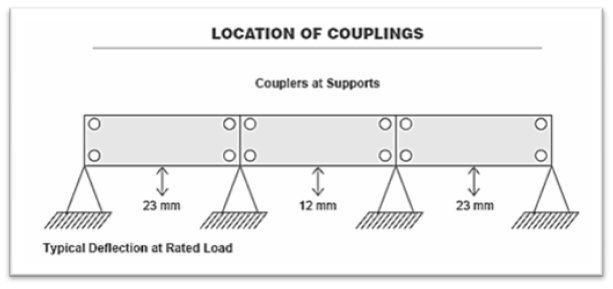
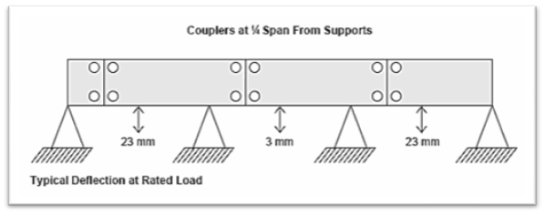
Cable tray deflection span 1
Cable tray deflection span 2

Location of Couplers.

The location of the coupler dramatically affects the deflection of a cable tray system under equal loading conditions. Testing indicates that the maximum deflection of the center span of a three-span cable tray run can increase four times if the couplers are moved from one-quarter span to above the supports. This can be a major concern for designers considering modular systems for tray and pipe racks.
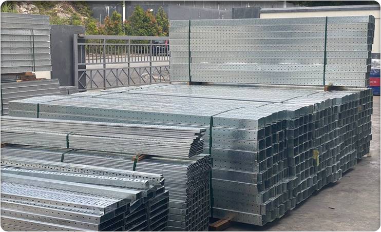
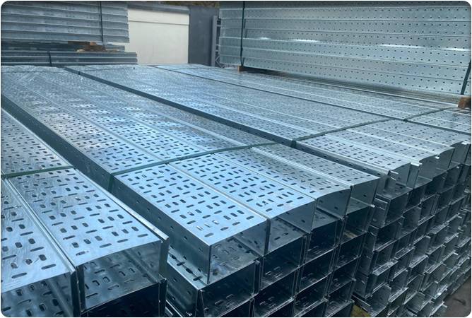
Coupler location reference 1
Coupler location reference 2

Frequently Asked Questions

Common questions about SAN Engineering cable tray systems in Malaysia.

Product Overview

What is a cable tray and what is it used for?

A cable tray is a rigid support structure that holds and routes electrical cables along an organised pathway. SAN Engineering manufactures cable tray systems for industrial and commercial installations, providing efficient cable routing that reduces tangling and damage while keeping cables accessible for maintenance and future modifications.

What types of cable tray does SAN Engineering supply?

SAN Engineering supplies cable tray in three bottom styles — ladder type, ventilated, and solid bottom. Ladder tray is the most common because it is cost-effective, while ventilated and solid-bottom trays suit applications needing extra cable bearing surface or mechanical protection. The SAN Engineering team can advise on the right type for your project.

Does SAN Engineering supply cable tray covers, accessories, and connectors?

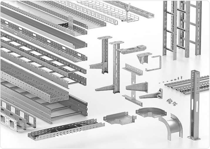
Yes. Along with straight sections, SAN Engineering supplies cable tray covers, fittings, connectors, and accessories used to change the size or direction of a run, so a complete cable tray system can be sourced from a single manufacturer.

Materials & Finishes

What materials are SAN Engineering cable trays made from?

SAN Engineering manufactures cable trays from corrosion-resistant steel, stainless steel, and aluminium alloys. Material selection depends on cost, the potential for corrosion, and electrical considerations, and the SAN Engineering team helps customers choose the most suitable option.

What finishes are available for SAN Engineering cable trays?

SAN Engineering offers corrosion-resistant finishes including hot-dip galvanizing (zinc), PVC, and epoxy coating. Each finish provides protection suited to different environments, and the right choice depends on where the cable tray will be installed.

Why is hot-dip galvanizing used on cable trays?

Hot-dip galvanizing coats the steel with a protective zinc layer that significantly improves resistance to corrosion and moisture. This extends the service life of the cable tray and makes it suitable for demanding indoor and outdoor environments, which is why it is a core finish offered by SAN Engineering.

Standards & Compliance

What standards do SAN Engineering cable tray systems comply with?

SAN Engineering cable tray systems, fittings, and accessories are manufactured in compliance with IEC 61537, NEMA VE 1 and VE 2, MS standards, and the NEC (ANSI/NFPA 70), meeting recognised local and international requirements for cable management.

What does NEMA VE 1 load class mean for cable tray selection?

NEMA VE 1 defines 12 load classes, designated by a span number and a load letter, where the rating must account for the cable weight plus any wind or snow loads. Specifying the lightest class compatible with the load is usually the most economical, and SAN Engineering can guide customers through this selection.

Can a wider cable tray hold more cable weight?

No — the load rating does not increase with tray width. A wider tray offers more volume but the same load capacity, so if the rating permits, cables can be piled deeper rather than wider. SAN Engineering can help select the correct width and class for the intended cable load.

Technical & Installation

How is the correct cable tray size determined?

Cable tray width and height depend on the number, size, spacing, and weight of the cables being carried. SAN Engineering offers a range of nominal widths and heights, and the team can help match the tray size to the cable schedule for your installation.

How do I choose the right fittings and bend radius?

Fittings change the size or direction of a cable tray run, and the bend radius should be based on the minimum bending radius of the cables, available space, and ease of cable pulling. Standard and custom radii along with various angle fittings are available from SAN Engineering.

Does deflection affect the structural performance of a cable tray?

Deflection mainly affects the appearance of an installation rather than structural integrity, and it is reduced when trays are run as continuous beams over multiple spans. Under the NEMA load test, a tray must support 150% of its rated load, and SAN Engineering cable trays are designed to meet these criteria.